Publicity: Existing and emerging defect detection methods in pipelines
Existing leak detection method
A number of existing leak detection methods are introduced and discussed below.
Passive observation: It is a "wait-and-see" approach in which engineers do nothing until leaks in pipe show themselves by causing water pond in streets, excessive ground settlement or water jets shooting from a pipe etc.. However, leakages have already caused considerable economic losses and inconvenience to the public when these effects show up.
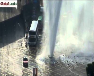
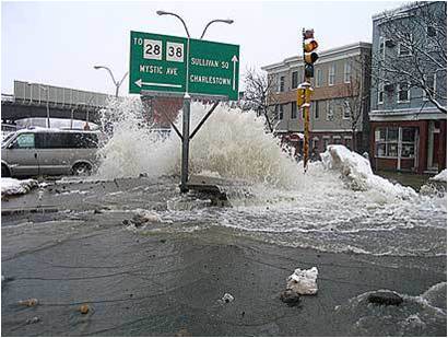
Pipe burst becomes observable to the public's eyes: (left) in Hong Kong; (right) in Canada
Water audit: It detects leaks be determining the amount of water loss in a water distribution system. A distribution system is divided into a number of districts. Districts are isolated individually by closing appropriate valves except at control points where portable flow meters are installed to measure water flows. Excessive water losses from the system are identified by either an inflow-outflow balance approach or comparing the ratio between the night-time minimum rate and the average daily rate of water flow and the “normal” ratios or to previously measured ratios of the same district. When excess loss is found in a district, the location of the leak can be narrowed-down by subdividing the district and measureing the water loss in the subdivisions. Traditional district audits are labour-intensive and costly. Because of technological advancement, there is a recent trend to install permanent flow meters that are connected telemetrically to a SCADA system. The transmitted flow rate data are automatically analyzed to detect unusual increases in flow patterns. From the experience with the water system, it can be determined whether an increase in flow rate is due to new leaks. District audits identify areas of the distribution system that have excessive leakage. However, water audit does not provide the exact location of leaks for crews to repair the leakage.
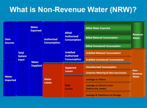
A water audit for water sources, water consumption, and non-revenued water. Courtesy: Campaign "What Our Water’s Worth" led by the Metropolitan Planning Council and Openlands , Chicago region, US
Acoustic devices: After an area of excessive leakage is identified, leak locations are commonly pin-pointed by acoustic devices. Crews are sent out to detect acoustic "leak noise" induced by water leaking from pressurized pipes with listening rods or microphones when they are walking along the pipe system. To improve pin-pointing accuracy, leak-noise correlators are also used together with sensors or hydrophones. To explain, "leak noise" are measured with sensors or hydrophones at two pipe contact points (usually fire hydrants or valves) that bracket the suspected location of a leak. Measured leak signals are transmitted from the sensors to the correlator wirelessly. The leak is usually located asymmetrically between the two measurement points and consequently there is a time lag between the measured leak signals. The time lag is computed to pin-point the leak location. Acoustic techniques are the most commonly used technique over the world, including HK, however, the technique is not efficient for plastic pipes because the "leak noise" in plasitc pipe is weaker and is of a lower frequency (below 50Hz) where human ears are less sensitive to.
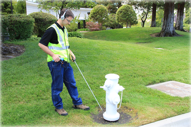
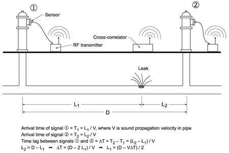
Leak detection by acoustic devices: (left) A worker detecting leaks using acoustic devices (from http://www.rfhunterinc.com/Metrotech-HL10.html). (right) Principle of leak-noise correlation (http://www.nrc-cnrc.gc.ca/ctu-sc/ctu_sc_n40).
Smart-ball or Sahara system: In this method, an acoustic sensor (the "Smart-ball" is a free-swiming sensor while a Sahara sensor is a tethered sensor) is inserted into a pipeline. For the "Smart-ball", the sensor travels with the water flow in the pipe freely. For the Sahara system, the Sahara sensor is propelled by the water flow while it is tethered. The sensor collects information about leaks and air pockets when it is in the pipe. The infomations are then transmitted to the ground. These techniques can be used without disruption to regular pipeline service. However, access points are required to insert sensors into the pipe system. For more information, please visit https://www.puretechltd.com.
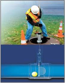
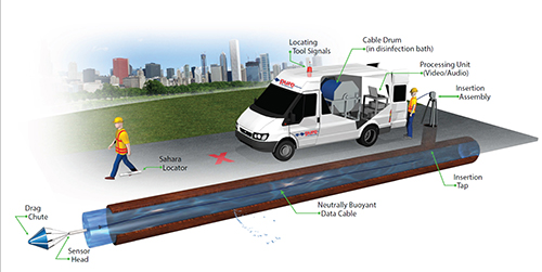
(left) The Smart-Ball. (right) The Sahara system. From Pure Technologies
Transient-based Leak and Blockage Detection
Waterhammer waves are generated when there are any changes in the pipe system (e.g. valve closures, pump failures, ...). While uncontrolled or unintended generation of waterhammer waves are damaging to pipe systems, waterhammer waves can be injected under control to detect leaks and blockages in pipe systems. Such approach is the transient-based technique. The working principle of the transient-based technique is that leaks and blockages in the pipe system induce reflections to the waterhammer waves. By analyzing the waterhammer waves, the location and size of the leaks or blockages can be detected.
Below are some examples of the effect of defects on waterhammer waves. The videos below show pipe flows driven by a reservoir at the left. There are valves at the right hand side of the two pipes which are initially open. When the valves at the right hand side are closed waterhammer waves are generated near the valves and the pressure (or head to be precise) increases. The waterhammer waves propagate to the left until they reach the reservoir and reflect. If there is a leak in the pipe, an additional reflection at the leak can also be seen.
Numerical simulations of waterhammer wave passing through (1)an intact pipe, and (2) a leaking pipe. The red line represent pressure (or head) in the pipe due to waterhammer waves.
(1) an intact pipe
(2) a leaking pipe
Another example is the experimentally measured pressure(or head) in a pipe with no blockage and a pipe with a blockage shown below. The difference in pressure measured is caused by the reflections due to the blockage.
Experimental results comparing the measured waterhammer wave pressure (or head to be precise) in (1) a pipe with no blockage, (2) a pipe with a blockage.
-
(1) A pipe with no blockage
-
(2) A pipe with blockage
Because defects induce changes to waterhammer waves (and thus the measured pressure), by analyzing the measured pressure of waterhammer waves in a pipe, the size and location of defects (e.g. leaks, blocks) can be detected.